Search the whole station Products News
Integrated ICT, Programming, and FCT Production Line
Project Case
With the increasing intelligence of the new energy vehicle industry and the maturation of autonomous driving, there is a growing number of sensing components in vehicles. The electrical performance testing of vehicle – mounted radar control boards is now facing unprecedented challenges. Under the rapid iteration of intelligent driving technologies, the traditional offline manual ICT and programming testing models, under the combined pressure of rising labor costs, prominent production capacity bottlenecks, and higher requirements for quality control precision, can no longer meet the manufacturing needs of automotive – grade products. This article will analyze the innovative path of automated testing for automotive electronic radar control boards from a technical perspective, providing practical electrical performance testing solutions for the industry.
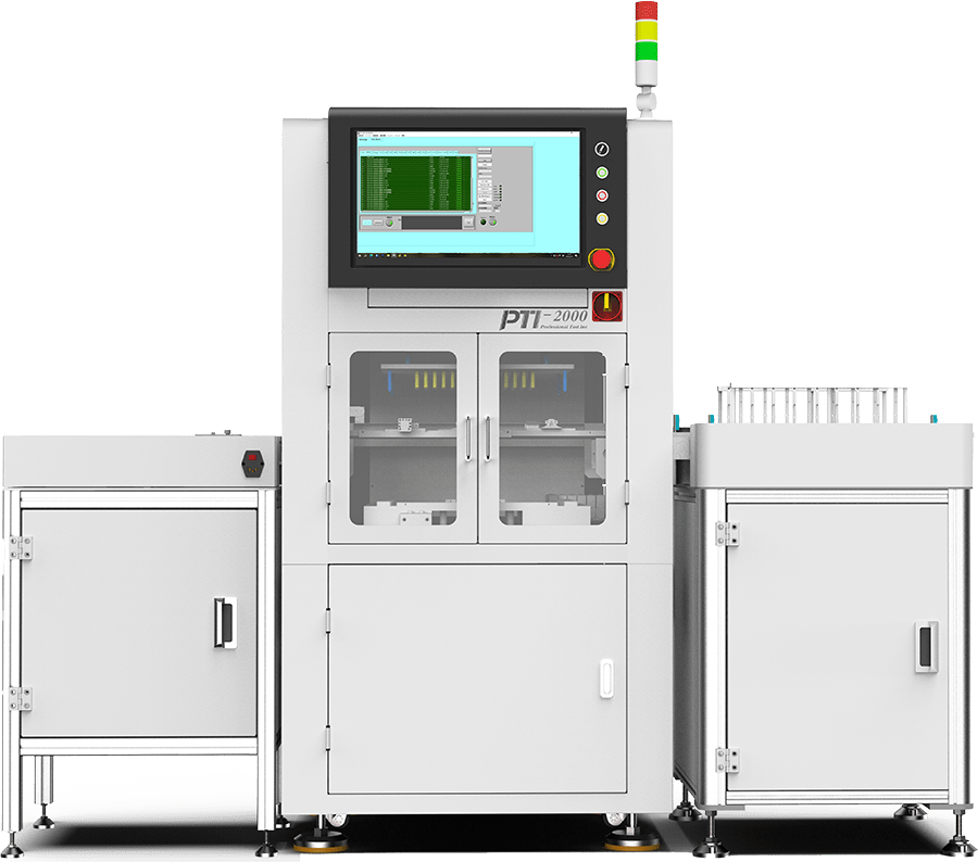
Adopt the PTI – 2000 series general testing framework to build an integrated production line of “connection table + testing machine (ICT + programming + FCT) + NG screening machine”
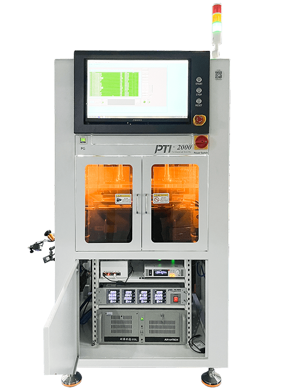
Hardware Structure
With the PTI – 300 test platform as the core, it integrates the PTI PM – 0040 multi – channel power meter (accuracy ±0.1% FS), the PTI PM – D3630 DC power supply (38V/30A wide – range output), the PTI100 test main control, and is matched with a general – purpose CAN box (supporting CAN FD 8Mbps communication), realizing the full – link coverage from power excitation to signal acquisition.
Software Coordination
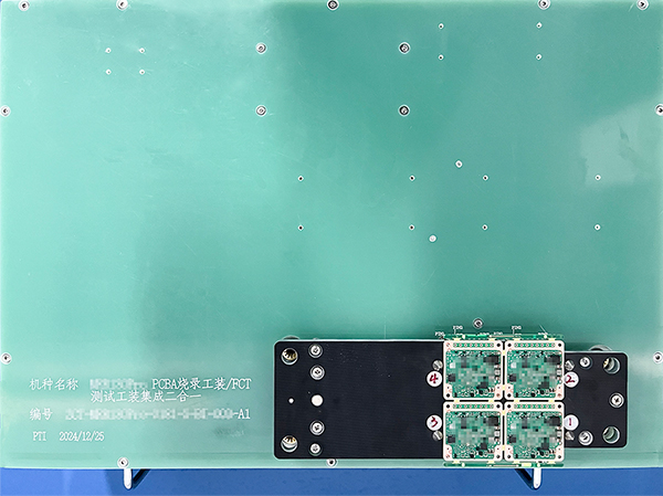
The test sequence is developed based on LabVIEW + TestStand, supporting 16 – channel parallel testing. Taking the 4 – panel test as an example, the system can automatically identify the panel coordinates and achieve independent testing of each single panel through the coordinate mapping algorithm, compressing the test cycle time to 61 seconds per piece.
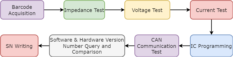
– Impedance Test:Utilizes the four-wire Kelvin testing method. Through the high-precision LCR meter built into the PTI-100, it measures impedance from 0.1mΩ to 20MΩ across a frequency range of 100Hz-100kHz, with test repeatability ≤0.5%. Taking the CAN terminal resistor test as an example, the system automatically applies a 100mA constant current source, collects the voltage drop to calculate the resistance value. The measured value is 119.373Ω (standard range: 115-125Ω), achieving an accuracy of ±0.8%.
– Open/Short Circuit Test:Supports multiple methods including constant voltage and constant current. Test thresholds are configurable up to 100mΩ (short circuit) and over 20MΩ (open circuit). It employs matrix switches to enable rapid scanning of 256 channels, with a missed detection rate <0.01%.
– Multi-Dimensional Programming:Integrates triple mechanisms of BOOTloader programming, APP firmware flashing, and OTP area encryption. Supports parallel programming via multiple interfaces (UART1 – UART4). The programming time for a 4MB program is controlled within 8 seconds, with a success rate of 99.98%.
– CAN Communication Test:Emulates an in-vehicle CAN network via the USBCANFD interface, transmitting 2000 test frames (including standard frames/extended frames/error frames). The measured bit error rate is 0.002%, meeting the requirements of ISO 11898-2:2016.
Functional Verification Module
Power Integrity Test:Simultaneously monitors 8 power rails including VCC_IN (11-12V) and VCC_5V (4.75-5.25V). Uses the PTI PM-0040 power meter to collect real-time parameters such as ripple (≤50mVpp) and transient response (<100μs). Example: VCC_5V measures 4.978V with 28mVpp ripple.
Version Management Test:Automatically queries hardware and software versions. Compares programmed files using the CRC32 checksum algorithm. Version consistency verification completes in <2 seconds.
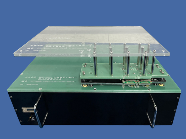
TEST FIXTURE
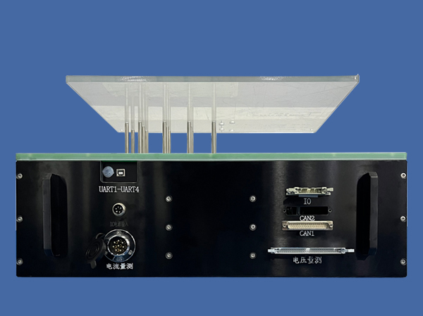
Interface Modularization:UART1 – UART4 (supporting 3.3V/5V level conversion)、DC power input (with reverse – connection protection)、Current measurement (range: 0.1mA – 30A)、Voltage measurement、IO interface (32 – channel bidirectional level)、Dual CAN interfaces (isolated design, anti – interference ≥2kV)、Voltage test (16 – bit ADC sampling)、Programmer interface (supporting both SWD/JTAG protocols)
Multi – Panel Adaptation Design:For 4 – panel products, the fixture uses a zoned voltage – division design. Independent testing of each single panel is achieved through 4 groups of independent probe sets, with a positioning accuracy of ±0.05mm to avoid signal crosstalk between panels (isolation >60dB).
| Efficiency & Cost Optimization | 60% increase in testing efficiency: Daily output per station reaches 1,920 pieces (4-panel format), meeting annual production demands of 500,000 units. |
| 35% reduction in labor costs: Eliminates 4-6 testing personnel per production line, saving over ¥800,000 annually. | |
| Upgraded Quality Control | Testing error rate controlled within 0.5%: Achieves 400% higher precision than manual testing. |
| 42% decrease in product repair rate: Drops from 6.8% to 4.0%, reducing repair costs by 280 units per 10,000 pieces (approx. ¥140,000 savings). | |
| Technical Scalability | Compatibility with millimeter-wave radar (24GHz/77GHz) and LiDAR control boards: Enables rapid model switching via software configuration. Interface docking structure: Facilitates model changes in <5 minutes, ideal for small-batch, multi-variety production scenarios. |
(Note: The technical parameters in the text are based on actual test data, and the specific solution can be customized according to product characteristics.)
 0
0